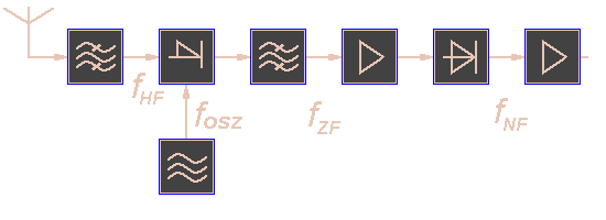

The superheterodyne receiver changes the rf frequency into an easier to process lower IF- frequency. This IF- frequency will be amplified and demodulated to get a video signal.
The Figure shows a block diagram of a typical superheterodyne receiver. The RF-carrier comes in from the antenna and is applied to a filter. The output of the filter are only the frequencies of the desired frequency-band. These frequencies are applied to the mixer stage. The mixer also receives an input from the local oscillator. These two signals are beat together to obtain the IF through the process of heterodyning. There is a fixed difference in frequency between the local oscillator and the rf-signal at all times by tuning the local oscillator. This difference in frequency is the IF. this fixed difference an ganged tuning ensures a constant IF over the frequency range of the receiver. The IF-carrier is applied to the IF-amplifier. The amplified IF is then sent to the detector. The output of the detector is the video component of the input signal.
Image-frequency Filter
A low-noise RF amplifier stage ahead of the converter stage provides enough selectivity to reduce the image-frequency response by rejecting these unwanted signals and adds to the sensitivity of the receiver.
Many older radar receivers do not use a low-noise pre-amplifier (RF stage) as the receiver front end; they simply send the echo signal directly to a crystal mixer stage. This has any disadvantages. It is possible for these receivers to receive two different stations at the same point of the dial.
Mixer Stage
The mixer stage is used to increase the received frequency to an intermediate frequency. The mixer also receives an input from the local oscillator. These two signals are beat together to obtain the IF through the process of heterodyning.
|
There aren't any components which can distinguish a negative
frequency of a positive frequency. therefore we can measure the
magnitude of the frequency only: |
The result is a second reception frequency as a „mirror image” around the intermediate frequency.
Assuming an intermediate frequency of 60 MHz, the local oscillator will track at a frequency of 60 MHz higher than the incoming signal. For example, suppose the receiver is tuned to pick up a signal on a frequency of 1030 MHz. The local oscillator will be operating at a frequency of 1090 MHz. The received and local oscillator signals are mixed, or heterodyned, in the converter stage and one of the frequencies resulting from this mixing action is the difference between the two signals, or 60 MHz, the IF frequency. This IF frequency is then amplified in the IF stages and sent on to the detector and audio stages.
Any signal at a frequency of 60 MHz that appears on the plate of the converter circuit will be accepted by the IF amplifier and passed on.
So on a receiver with no RF amplifier, the
input to the converter is rather broadly tuned and some signals other than
the desired signal will get through to the input jack of the converter
stage. Normally these other signals will mix with the local oscillator
signal and produce frequencies that are outside the bandpass of the 60 MHz
IF amplifier and will be rejected. However, if there is a station operating
on a frequency of 1150 MHz, and this signal passes through the rather broad
tuned input circuit and appears on the input jack of the converter stage, it
too will mix with the local oscillator and produce a frequency of 60 MHz
IF Filter
This filter must filter the desired intermediate frequency out from the mixture frequencies arisen in the mixer stage. It is designed as one or more bandpasses.
Normally, the bandpass is as narrow as possible without affecting the actual signal energy. When a selection of pulse widths is available, such as short and long pulses, the bandpass must be able to match the bandwidth of the two different signals.
IF- Amplifier
The IF amplifier has the capability to vary both the bandpass and the gain of a receiver. After conversion to the intermediate frequency, the signal is amplified in several IF- amplifier stages. Most of the gain of the receiver is developed in the IF amplifier stages. The overall bandwidth of the receiver is often determined by the bandwidth of the IF stages. Gain must be variable to provide a constant voltage output for input signals of different amplitudes.
Detector
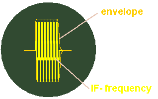
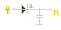
The detector in a microwave receiver serves to convert the IF pulses into video pulses.
 
|
  The simplest form of detector is the diode detector. It detects the pulse envelope: The condenser has got the function of a lowpass and blocks the IF- frequency. |
Video Amplifier
The video amplifier receives pulses from the detector and amplifies these pulses for application to the indicating device. A video amplifier is fundamentally an RC coupled amplifier that uses high-gain transistors. However, a video amplifier must be capable of a relatively wide Frequency response. The output stage of the receiver is normally an emitter follower. The low-impedance output of the emitter follower matches the impedance of the cable. The video pulses are coupled through the cable to the indicator for video display on the crt.
Local Oscillator
The local oscillator excite a frequency for mixing with the incoming signal to get the intermediate frequency.
Most radar receivers use megahertz intermediate frequency (IF) with a value between 30 and 75 megahertz. The IF is produced by mixing a local oscillator signal with the incoming signal. The local oscillator is, therefore, essential to efficient operation and must be both tunable and very stable. For example, if the local oscillator frequency is 3,000 megahertz, a frequency change of 0.1 percent will produce a frequency shift of 3 megahertz. This is equal to the bandwidth of most receivers and would greatly decrease receiver gain.
The power output requirement for most local oscillators is small (20 to 50 milliwatts) because most receivers use crystal mixers that require very little power.
The local oscillator output frequency must be tunable over a range of several megahertz in the 4,000-megahertz region. The local oscillator must compensate for any changes in the transmitted frequency and maintain a constant 30 or 75 megahertz difference between the oscillator and the transmitter frequency. A local oscillator that can be tuned by varying the applied voltage is most desirable.
The exiting frequency is either higher or lower than the incoming frequency. An RF amplifier stage ahead of the converter stage provides enough selectivity to reduce the image-frequency response by rejecting these unwanted signals and adds to the sensitivity of the receiver.